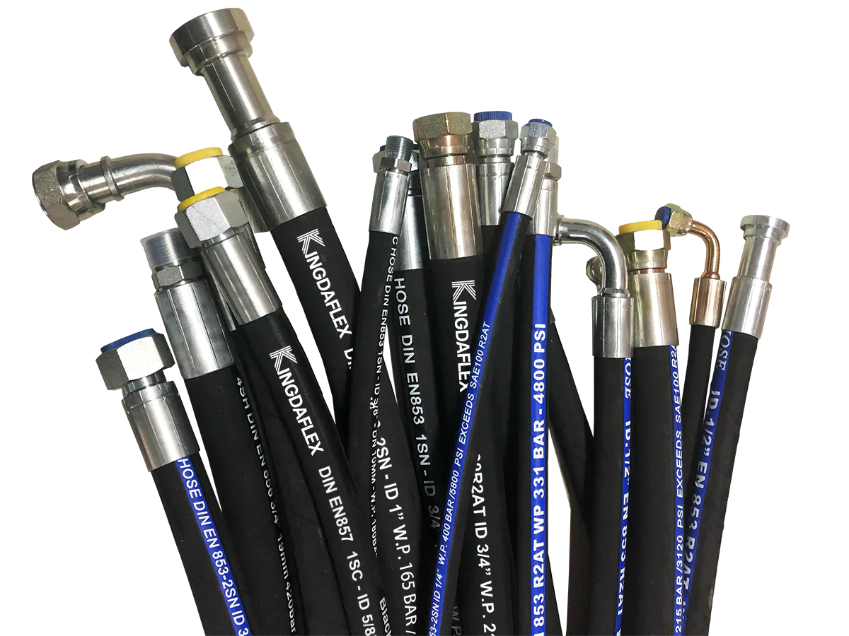
A hydraulic hose, rated for 2,000 to 6,000 psi pressures and -40°C to 121°C temperatures under SAE 100R standards, transports synthetic or mineral oils using an inner synthetic rubber lining, wire braid or spiral reinforcement, and a weather-resistant cover to power 85% of heavy machinery.
Liquid power transmission relies on incompressible fluid flowing under high pressure to turn pump energy into mechanical force inside cylinders and motors. A typical hydraulic hose operates as a flexible conduit, maintaining fluid flow across moving joints where steel pipes fracture under 150 Hz vibration levels.
Flexible conduit designs allow high-pressure fluid lines to move freely along excavator arms without structural failure.
Because motion causes continuous friction, outer rubber covers must withstand ISO 6945 abrasion tests, which require surviving 2,000 scraping cycles under a 25 N vertical force. When equipment operates at 90% capacity, high friction wears down unprotected surfaces, leading to system leaks that cause average repair costs of $1,200 per hour.
| Component Layer | Primary Material | Function & Standard |
| Inner Tube | Nitrile (NBR) or PTFE | Chemical resistance, fluid containment |
| Reinforcement | High-tensile steel wire | Pressure support up to 6,000 psi (SAE 100R12) |
| Outer Cover | Neoprene / Polyurethane | Abrasion resistance (ISO 6945) |
Pressure retention depends directly on wire braid patterns, where four-spiral steel configurations handle 25% higher surge pressures than standard two-wire braids. Modern manufacturing facilities tested 500 hose assemblies in 2024, demonstrating that spiral wire layouts resist fatigue through 1,000,000 continuous pressure impulse cycles.
-
Single-Wire Braid: Supports medium pressures up to 3,000 psi in tractor steering components.
-
Double-Wire Braid: Handles up to 5,000 psi in forestry harvesting heads built in 2023.
-
Four-Spiral Wire: Holds up to 6,000 psi under severe pressure spikes in mining excavators.
The strength of the wire reinforcement allows hydraulic fluid to enter actuators without ballooning the inner walls or losing line pressure. Fluid enters the cylinder bore at 45 liters per minute, pushing the internal piston forward to lift 12-ton loads on construction job sites.
Piston movement converts hydraulic fluid pressure directly into linear physical force to operate heavy machinery attachments.
After extending the piston, fluid travels back to the main reservoir through a return line operating below 250 psi. Test data from 2025 showed that maintaining clean fluid through 10-micron filtration prevents 80% of valve sticking incidents in industrial pump stations.
Chemical compatibility between the inner tube and the fluid prevents inner wall degradation during extended operation. Synthetic NBR rubbers hold up against petroleum-based oils, whereas specialized PTFE liners are required for fire-resistant fluids operating above 100°C.
-
Petroleum Oils: Pair with NBR inner tubes to prevent rubber swelling.
-
Water-Glycol Mixtures: Require specialized EPDM or synthetic linings.
-
Biodegradable Ester Fluids: Demand synthetic materials rated for chemical oxidation resistance.
Selecting compatible materials prevents inner tube flaking, which otherwise blocks narrow valve orifices downstream. In 2022, laboratory analysis of 300 failed pumps revealed that 45% of seal failures originated from rubber debris shed by incompatible hose linings.
Temperature ratings dictate how long rubber polymers maintain flexibility before cracking under continuous stress. Standard hydraulic hose materials sustain cold flexibility down to -40°C in arctic logging equipment, while synthetic outer covers prevent heat degradation up to 121°C near engine manifolds.
Extreme thermal shifts degrade rubber elasticity, requiring strict temperature checks during seasonal maintenance cycles.
Beyond temperature controls, overall system safety relies on keeping fluid pressure below rated working limits. Industry standards require a 4:1 safety factor, meaning a line rated for 4,000 psi working pressure must reach a 16,000 psi burst threshold before structural wall failure occurs.
Working Pressure: 4,000 psi --> Burst Threshold: 16,000 psi (4:1 Safety Ratio)
Maintaining this 4:1 safety margin protects technicians from fluid injection injuries caused by micro-pinhole leaks under high pressure. Safety logs from 2021 recorded that 60% of high-pressure fluid leaks occurred within 5 inches of the metal crimp fitting.
Proper crimping procedure secures the outer metal ferrule onto the inner hose stem using precise hydraulic die sets. A 0.5 mm error in crimp diameter reduces assembly holding strength by 35%, causing the fitting to blow off during sudden pressure surges.
[Outer Ferrule] + [Reinforced Hose] + [Inner Stem] ==(Hydraulic Crimp Die)==> Leak-Free Assembly
-
Step 1: Measure outer hose diameter with digital calipers to verify size tolerances.
-
Step 2: Select matching crimp dies based on manufacturer specifications from 2024 charts.
-
Step 3: Compress the ferrule until the final outer crimp diameter matches specification within +/- 0.1 mm.
Correctly crimped assemblies undergo 100% proof testing at 1.5 times working pressure before field installation. Field data from 2023 confirmed that pre-tested assemblies experienced 95% fewer unexpected line ruptures during their initial 2,000 operating hours.